Install VM Launchpad
PaletteAI VM Launchpad is a bootable ISO that you install on bare metal or Edge devices to create a cluster with Virtual Machine Orchestrator (VMO) preconfigured. Install the appliance on each device that serves as a node in your VMO cluster, and link the nodes together to form your cluster. After you deploy your cluster, log into VM Launchpad to do an initial configuration, and create your first VM.
Hardware Requirements
Each device where you install the VM Launchpad ISO must meet the following hardware requirements.
| Component | Minimum | Recommended | Additional Information |
|---|---|---|---|
| CPU | Intel or AMD64 CPU with 8 cores | Intel or AMD64 CPU with 8 cores | - |
| RAM | 24 GB | 256 GB or more | Assumes the deployment of 20 VMs per node multiplied by the median RAM per VM. |
| Network Adapters | 4 x 1 Gbps (2 bonded for management, 2 bonded for VM data) | 4 x 10 Gbps (2 bonded for management, 2 bonded for VM data) | Cilium bridges VMs onto the data NICs. Review Network Configuration Considerations for details. |
| Disks | Local disk of at least 750 GB for the OS boot | Local disk of at least 750 GB for the OS boot | Provision at least 750 GB before you install the appliance. The installer partitions this disk automatically. |
Advanced storage configuration. If only two network adapters are available, you can deploy with two NICs bonded for all traffic plus two 16 Gbps Fiber Channel (FC) adapters dedicated to storage. FC-attached storage can also serve as raw disks for Piraeus consumption without a CSI driver, though this is not the typical configuration. Refer to Network Configuration Considerations for supported layouts.
Prerequisites
Plan your host network layout before you install the appliance. VM Launchpad supports specific bond, bridge, and VLAN configurations, and network changes are difficult to make after installation. Review Network Configuration Considerations to choose a supported layout and prepare your switch port configuration.
-
Configure the host network with a
br0bridge that matches one of the supported layouts described in Network Configuration Considerations. -
Reserve a virtual IP address (VIP) for the VM Launchpad management cluster. The VM Launchpad installation process assigns the VIP and uses it for load balancing and high availability. Ensure all nodes in the VM Launchpad management cluster can access the VIP.
-
If you have an Ubuntu Pro subscription, you can provide the Ubuntu Pro token during the VM Launchpad installation process. This is optional but recommended for security and compliance purposes.
-
(Secure Boot only) If you enable Secure Boot on your server, register Spectro Cloud's trusted software certificate (
MOK.der) so the appliance can boot and run storage components correctly. You can use either of the following methods:-
BIOS method - Use one of the following collapsible sections below if your server supports uploading the certificate through firmware. This applies to Dell servers with Unified Extensible Firmware Interface (UEFI) and Hewlett Packard Enterprise (HPE) servers with iLO 5. Complete these steps before you boot the appliance ISO.
Install Secure Boot on Hewlett Packard Enterprise iLO 5
Before you begin, ensure that you have iLO 5 access with privileges to launch the remote console and change BIOS settings. You also need the
MOK.dercertificate file on your local computer. Skip to step 4 if you have already downloaded the certificate file.- Navigate to Artifact Studio.
- Select the version corresponding to your VM Launchpad installer. Then, select Show Artifacts. The artifact list appears.
- Download the MOK Key for Secure Boot file.
- Power on or reboot the server. When prompted during Power-On Self-Test (POST), press F9 to enter System Utilities.
- Select System Configuration and press ENTER.
- Select BIOS/Platform Configuration (RBSU) > Server Security > Secure Boot Settings > Advanced Secure Boot Options.
- Select DB – Allowed Signatures Database > Enroll Signature. If Secure Boot is currently enabled, the Enroll Signature option will be unavailable. Temporarily disable Secure Boot and repeat the process.
- Drag the
MOK.derfile from your desktop onto the iLO Remote Console window. iLO mounts it as a virtual USB device automatically. - Confirm any prompts.
- Verify that the new entry appears under DB – Allowed Signatures Database > View Signatures.
- Press ESC to exit the menus until the Save and Exit option is available.
- Save your changes. Exit the menu and reboot the server.
Install Secure Boot on Dell Servers with UEFI
Before you begin, you need the
MOK.dercertificate file on your local computer. Skip to step 4 if you have already downloaded the certificate file.-
Navigate to Artifact Studio.
-
Select the version corresponding to your VM Launchpad installer. Then, select Show Artifacts. The artifact list appears.
-
Download the MOK Key for Secure Boot file.
-
Power on the server. Execute the following command to create a virtual CD/DVD drive containing an ISO file with the
MOK.dercertificate. Alternatively, you can save the file to a FAT32-formatted USB drive.mkisofs -output key.iso -volid cidata -joliet -rock MOK.der -
Reboot the server. When the Dell logo appears, press F2. The System Setup menu opens.
-
Select System BIOS > Boot Settings.
-
Ensure that the Boot Mode is set to UEFI.
-
Press ESC to return to Boot Settings.
-
Select System Security > Secure Boot Settings.
-
Toggle Secure Boot to Enabled and Secure Boot Policy to Custom.
-
Select Secure Boot Custom Policy Settings > Authorized Signature Database (db).
-
Select Import New Entry. Then, select the virtual CD/DVD drive or USB drive containing the
MOK.derfile. -
Save your changes. Press ESC to return to Authorized Signature Database (db).
-
Select View Entries. The
MOK.derfile shows in the database as DRBD Module Signing. -
Save your changes. Exit the menu and reboot the server.
-
MokManager method - Use this method if your BIOS does not support certificate upload or if BIOS enrollment did not load the storage module successfully. Boot the host from the Appliance ISO, and then complete the MokManager steps in Install before you select a disk.
-
Install VM Launchpad
-
Navigate to Artifact Studio to download the VM Launchpad ISO.
-
In the VM Launchpad section, use the drop-down menu to select the version and appliance variant, and select Show Artifacts.
The VM Launchpad appliance is available in the following variants, which differ by FIPS compliance and storage backend. In the drop-down menu, each version lists its storage backend in parentheses, such as
(piraeus)or(portworx), and FIPS builds carry a FIPS label. A FIPS and a non-FIPS build of the same backend are otherwise identical in the list, so use the FIPS label to tell them apart. Choose the variant that matches your compliance and storage requirements.Variant FIPS Compliance Appliance Storage Backend Choose This Variant When FIPS Piraeus FIPS-compliant Piraeus/LINSTOR replicated block storage You require a FIPS-compliant appliance. Non-FIPS Piraeus Not FIPS-compliant Piraeus/LINSTOR replicated block storage You want open source replicated block storage and do not require FIPS. Non-FIPS Portworx Not FIPS-compliant Portworx enterprise distributed storage Your organization is standardized on Portworx or Everpure (formerly Pure Storage) FlashArray. infoThe Slim ISO and the content bundle must match on FIPS mode. A FIPS content bundle pairs only with the Piraeus backend. A non-FIPS content bundle pairs with either the Portworx or the Piraeus backend.
-
The following table describes the artifacts available for VM Launchpad.
Artifact Description Content bundle (including Ubuntu) Content bundle to pair with the slim Appliance ISO. Includes the OS content and VM Launchpad packs. Appliance ISO Slim ISO without an embedded content bundle. Upload the content bundle separately after installation. MOK Key for Secure Boot Machine Owner Key (MOK) to use for secure boot with MokManager. -
Download both the Appliance ISO and the Content bundle (including Ubuntu). Download the MOK Key for Secure Boot if you use secure boot on your host.
-
Boot your device using the VM Launchpad ISO. On the Grand Unified Bootloader (GRUB) menu, allow the VM Launchpad to select the Palette Edge Interactive Installer boot option automatically
dangerDuring the bootstrap process, the TUI performs a pre-installation check that checks all disks for partitions left behind by previous Kairos installations. This helps prevent stale partitions from causing unpredictable installation behavior.
If any disks are affected, they are pre-selected for wiping; you can select additional disks as well. Wiping disks is optional and must be confirmed on the following screen. Carefully verify the selected disks before proceeding.
-
(Secure Boot only) If you did not enroll the certificate through BIOS, expand the following section and complete the MokManager steps before you continue.
Enroll DRBD Signing Key with MokManager
Before you begin, you need Spectro Cloud's
MOK.dercertificate file on the server. Skip to step 5 if you already have the certificate file at/tmp/MOK.der.-
Navigate to Artifact Studio.
-
In the section for your appliance, use the drop-down to the appropriate appliance version. Then, select Show Artifacts. The artifact list appears.
-
Download the MOK Key for Secure Boot file.
-
Copy the certificate file to your server at
/tmp/MOK.der.scp <downloaded-filename>.der <username>@<host-ip>:/tmp/MOK.derReplace
<downloaded-filename>with the name of the downloaded certificate file,<username>with your username on the host, and<host-ip>with the IP address of the host. -
On your server, copy
mmx64.efito the EFI boot partition. The appliance includes the file at/usr/lib/shim/mmx64.efi, but it might not be automatically copied to the EFI partition. MokManager needs this file atEFI/boot/mmx64.efito launch at reboot. If your host uses a different disk, uselsblk --fsto identify the FAT32 EFI partition, and replace/dev/sda1in the following code block with the correct partition.MP=/tmp/cos_grub_fix
mkdir -p "$MP"
mount /dev/sda1 "$MP"
install -m 0755 /usr/lib/shim/mmx64.efi "$MP/EFI/boot/mmx64.efi"
ls -la "$MP/EFI/boot/"
sha256sum /usr/lib/shim/mmx64.efi "$MP/EFI/boot/mmx64.efi"
umount "$MP"
rmdir "$MP" -
Verify both
sha256sumoutputs match. This confirms the copy is intact. -
Import the DRBD signing key.
sudo mokutil --import /tmp/MOK.dertipIf
mokutil --importreturnsSKIP: already in db, the DRBD key is already enrolled in firmwaredb, which causesmokutilto skip the import. Remove the key fromdbfirst, using BIOS orracadm bioscert delete, and try again. -
When prompted, set a temporary password. This password is only used once.
-
Confirm the import is queued. The DRBD signing key appears in the output.
sudo mokutil --list-new -
Reboot the host.
sudo reboot -
When the system reboots, a blue MokManager screen appears. Select Enroll MOK.
tipIf the blue MokManager screen does not appear at reboot, confirm
mmx64.efiis present at\EFI\boot\mmx64.efion the ESP. Repeat step 5 if it is not. -
Select View key 0 and confirm it is the DRBD signing key.
-
Select Continue.
-
Select Yes to confirm enrollment.
-
Enter the temporary password you set in step 8.
-
Select Reboot. The system continues booting normally.
-
After boot, confirm the key is enrolled in the MOK list and visible to the kernel.
sudo mokutil --list-enrolled | grep -i "DRBD Module Signing" -
Confirm the kernel has the key in its keyring. The DRBD signing key appears in at least one of these outputs.
sudo keyctl list %:.machine 2>/dev/null | grep -i drbd
sudo keyctl list %:.platform 2>/dev/null | grep -i drbd
-
-
From the VM Launchpad Interactive Installer screen, select the disk to install the appliance on. Press ENTER to proceed to the next screen.
dangerEnsure you select the correct disk. The installation process erases all content on the target disk.
-
On the Installation Options screen, select what the installer does after the installation completes. Press ENTER to begin the installation process. After the installation completes, disconnect the ISO. The following table describes the available options.
Option Description nothing Keeps the system powered on after installation. reboot Automatically reboots the system. poweroff Powers off the system. -
On the GNU GRUB screen, select Palette eXtended Kubernetes Edge Registration.
-
On the Palette TUI screen, press F2 to begin configuring your Edge host.
-
In the Palette TUI, provide credentials for the initial account. Use this account to log in to Local UI and access the node through SSH.
Field Description Username Provide a username to use for the account. Password Enter a password for the account. Confirm Password Re-enter the password for confirmation. Password Expiration (Optional) Set a date for the password to expire. Press ENTER to continue.
-
In the Palette TUI, the available configuration options appear. Use the TAB key or the up and down arrow keys to switch between fields. When you make a change, press ENTER to apply the change. Use ESC to go back.
-
In Hostname, check the existing hostname and, optionally, change it to a new one.
-
In Network Adapter, select a network adapter to configure. By default, network adapters request an IP address automatically from the Dynamic Host Configuration Protocol (DHCP) server. The Classless Inter-Domain Routing (CIDR) block of each adapter's possible IP address appears on the Network Adapter screen.
On the configuration page for each adapter, you can switch the IP addressing scheme from DHCP to static IP. In static IP mode, provide a static external IP address, subnet mask, and the default gateway address. A static external IP address removes the existing DHCP settings.
-
(Optional) Specify a Virtual Local Area Network (VLAN) ID on the configuration page of each network adapter. A VLAN ID segments network traffic on the same physical network interface for network isolation. If you assign a VLAN ID, the VM Launchpad host tags all outgoing packets from that adapter with the specified VLAN identifier.
-
(Optional) Specify the MTU for your network adapter. The MTU defines the largest packet size, in bytes, that the interface can send without fragmentation. Press ENTER to apply the change.
-
In DNS Configuration, specify the IP addresses of the primary and secondary name servers. Optionally, specify a search domain. Press ENTER to apply the change.
-
In NTP Configuration, specify one or more NTP servers. For example,
0.pool.ntp.organd1.pool.ntp.org. -
After you confirm the configurations, navigate to Logout and press ENTER to complete the configuration. The terminal screen displays the hostname and network information of your VM Launchpad host. Verify that all displayed information is consistent with your configurations.
Configure Network Settings
-
In your browser, go to
https://<host-ip>:5080. Replace<host-ip>with the IP address of your VM Launchpad host. If you have access to the VM Launchpad host terminal, the Local UI address appears on the terminal screen. If you have changed the default port, replace5080with your configured Local UI port. -
Log in with the username and password you created during installation.
-
If you need to change the interface used for management traffic, locate the Management Interface field and select the interface to use. Local UI can override the management interface selected during TUI configuration. Valid candidates include physical NICs, bonds (when not enslaved to another bond or a bridge), VLAN child interfaces, and bridges (with or without an IP address). A NIC or bond that is enslaved to a bond or bridge, or that has VLAN children, is not a valid candidate.
warningChanging the management interface may cause Local UI connectivity loss.
-
In the Network interfaces section, beside Bonds, select Create.
-
Complete the fields on the Create Bond screen and select Confirm.
Parameter Description Name Enter a name for the bond. For example, bond0.Bond type Select Static, DHCP, or None for IP address settings. Use None for an L2-only bond with no IP configuration, such as when the bond is enslaved to a bridge. Member interfaces Select one or more Network Interface Cards (NICs) for the bond. Bonding mode Select the bonding mode for the bond. This must match your physical switch port configuration. Link monitoring interval Select time in milliseconds. MTU Leave the default value or adjust to 9000 for jumbo frames. DNS Enter one or more DNS server IP addresses. IP Address For static bonds only, enter the IP address for the bond. Subnet mask For static bonds only, enter the subnet mask for the bond. Gateway For static bonds only, enter the gateway IP address for the bond. warningThis change may cause Local UI connectivity loss.
-
In the Network interfaces section, beside Bridges, select Create.
-
Complete the fields on the Create Bridge screen and select Confirm.
Parameter Description Name Enter a name for the bridge. For example, br0.Member interfaces Select one or more bonds for the bridge. Enable STP Enable Spanning Tree Protocol (STP) to prevent network loops when the bridge has more than one member interface. Leave off for single-member bridges. Config type Select Static, DHCP, or None for IP address settings. Use None for an L2-only bridge with no IP configuration, such as when the bridge carries only VM tenant VLAN traffic. MTU Leave the default value or adjust to 9000 for jumbo frames. DNS Enter one or more DNS server IP addresses. IP Address For static bridges only, enter the IP address for the bridge. Subnet mask For static bridges only, enter the subnet mask for the bridge. Gateway For static bridges only, enter the gateway IP address. warningThis change may cause Local UI connectivity loss.
Link Edge Hosts
For a multi-node cluster, link the hosts together after you configure their network settings and before you upload the content bundle. Linking gives the hosts the network and security infrastructure to identify each other and communicate securely. If you deploy a single-node cluster, skip this section and continue to Upload the Content Bundle.
You designate one host as the leader and link the remaining hosts to it as followers. You upload the content bundle to the leader, which syncs it to the followers, and you create the cluster from the leader.
The VM Launchpad appliance enables multi-node support by default, so you don't need to edit user data to link hosts. Skip the user-data prerequisites on the Link Hosts page and start at the procedure: from the leader's Local UI, select Linked Edge Hosts, generate a token, and enter that token on each follower host to link it. For the full steps, refer to Link Hosts.
After every host appears in the Linked Edge Hosts table on the leader, continue to Upload the Content Bundle.
Upload the Content Bundle
Before you create a cluster, upload the content bundle. The content bundle provides the OS content and VM Launchpad packs that the cluster profile requires. For a multi-node cluster, upload the bundle to the leader host, which syncs it to the linked follower hosts.
You can upload the bundle from the appliance's Local UI or with the Palette CLI. Use the Palette CLI if you reach the appliance over a VPN or a slow connection. A browser upload of a large bundle is unreliable on those connections, while the Palette CLI uploads the bundle in parallel chunks and resumes an interrupted upload.
Upload with Local UI
-
Log in to the appliance's Local UI.
-
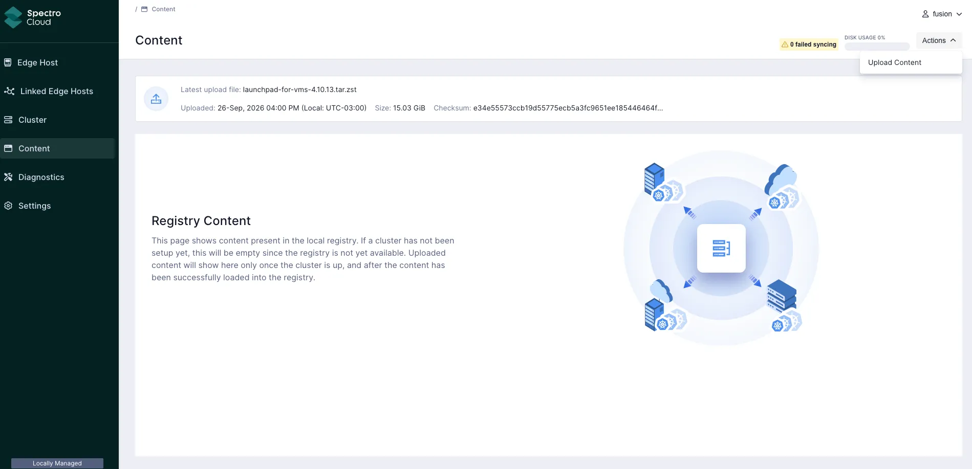
From the left main menu, select Content.
-
In the upper right, select Actions > Upload Content.
-
Select the content bundle file, such as
launchpad-for-vms-<version>.tar.zst, and upload it. The upload might take several minutes because the bundle is large. -
Confirm the upload. The Content page displays the latest upload file, upload time, size, and checksum, and updates the Disk Usage and syncing status. The registry content appears on this page only after the cluster is up and the content has loaded into the local registry.
For the full Local UI upload reference, including prerequisites and the Local UI port, refer to Upload Content Bundle with Local UI. After the upload finishes, continue to Create VM Launchpad Cluster.
Upload with Palette CLI
The Palette CLI runs on a workstation and sends the bundle to the leader host over the network. It authenticates with an
upload token that the host generates, so you do not need a Palette account or palette login for this upload. For a
single-node cluster, use your only host wherever these steps refer to the leader host.
Before you start, confirm the following:
-
You have a Linux or macOS workstation where you can run
sudo. The Palette CLI supports Linux on AMD64 and ARM64, and macOS on ARM64. -
The workstation can reach the leader host's IP address on TCP port 5082. The upload service uses this port, not the Local UI port (5080 by default).
-
The content bundle you downloaded from Artifact Studio is on the workstation.
-
You can SSH to the leader host with the account you created in the Palette TUI. Reading the upload token requires
sudoon the host.
-
In the Palette CLI section of the CLI Tools page, select the tab for your workstation's operating system and architecture, and copy the Download URL from the first row. The first row lists the highest Palette CLI version, which also works with earlier VM Launchpad versions.
-
Download the Palette CLI, make it executable, move it to a directory in your
PATH, and confirm that it runs.curl --location --output palette <download-url>
chmod +x palette
sudo mv palette /usr/local/bin/palette
palette versionReplace
<download-url>with the URL you copied. -
SSH to the leader host.
ssh <username>@<host-ip>Replace
<username>with the username of the account that you created in the Palette TUI and<host-ip>with the leader host's IP address. -
Read the upload token, and copy it.
sudo cat /opt/spectrocloud/.upload-auth-tokenClose the SSH session after you copy the token. The host generates a new token each time its Palette agent restarts, so read the token right before you upload.
-
Upload the content bundle to the leader host.
palette content upload --file <bundle-path> --token <upload-token> <host-ip>Replace
<bundle-path>with the path to the content bundle, such aslaunchpad-for-vms-<version>.tar.zst,<upload-token>with the token from step 4, and<host-ip>with the leader host's IP address.If the upload is interrupted, run the same command again, and the Palette CLI resumes the upload instead of starting over. If the CLI reports that the host rejected the token, repeat step 4 to read the current token, and then run the command again with it.
If you host the bundle on a web server or object store that the workstation can reach, you can stream it instead of copying it to the workstation. In the command, replace
--file <bundle-path>with--src-url <bundle-url>, where<bundle-url>is the URL of the bundle. The URL must support HTTP range requests. For all supported flags, refer tocontent upload. -
Wait for the Palette CLI to finish. After the transfer reaches 100 percent, the host extracts the bundle and imports its content into the local registry, which can take up to 30 minutes for a large bundle. The CLI waits for this step and displays the following message when it finishes.
Example Outputextraction complete: content is ready on the host
After the Palette CLI reports that the content is ready, log in to the leader host's Local UI and continue to Create VM Launchpad Cluster.
Create VM Launchpad Cluster
-
From the left main menu, select Cluster.
-
Select Create cluster.
-
Complete the Basic Information fields and select Next.
Parameter Description Cluster name Name of the cluster. Tags Key-value pairs to provide metadata about your cluster. -
The default VMO Appliance full stack profile loads. The following table describes each pack in the profile. After you review the cluster profile, select Next.
infoIf you installed the appliance from the slim Appliance ISO, upload the content bundle before this step. Refer to Upload the Content Bundle.
Components list of a VM Launchpad cluster
Component Pack Name Purpose Edge Native BYOI edge-native-byoiNative Ubuntu OS. Kubernetes edge-k8sKubernetes platform. Cilium cni-cilium-fipsCNI and network policy. Multus support for VM networking. Piraeus piraeus-operatorStorage backend. Provides StorageClass for VM disks. Zot zot-registry-fipsOCI registry. Stores container images for air-gapped deployments. Registry Connect registry-connectEnables integration with OCI-compliant registries. Required config required-config-1Initial configuration before continuing. MetalLB lb-metallb-helmLoad balancer implementation for bare metal. Assigns the platform IP address. Traefik traefikSingle ingress controller. Provides TLS termination, path-based routing, and the load balancer IP address. Required config required-config-2Second configuration before continuing. Keycloak keycloakOIDC identity provider. Handles login, user, and group management, and token issuance. Shared k8s-oidcclient with Kubernetes API and Headlamp.Headlamp headlampKubernetes cluster explorer. Alternative UI for raw Kubernetes resources. Victoria Metrics victoria-metrics-clusterOptional long-term metrics storage. Supports PromQL queries when EXTERNAL_METRICS_URLis configured.OTel Collector opentelemetryMetrics pipeline. Receives OTLP from node-agent and forwards metrics to VMO Manager, or Victoria Metrics. VMO virtual-machine-orchestratorPrimary UI and API gateway. Manages VMs, templates, golden images, access policies, configuration, and dashboards. VM Migration Assistant vm-migration-assistantMigrates VMs from VMware vSphere to VMO. Additionally, the VMO Manager pack bundles the following services.
Component Pack Name Purpose cert-manager virtual-machine-orchestratorIssues and renews TLS certificates. Single platform CA for all components. KubeVirt virtual-machine-orchestratorVirtual machine runtime. Manages VirtualMachine, VirtualMachineInstance, and DataVolume resources. CDI virtual-machine-orchestratorContainerized Data Importer. Handles disk image uploads, imports, and clones. -
On the Profile Config wizard step, complete the following fields for each section. Select Next when finished.
Networking
Parameter Description Pod Network Range IP address range assigned to internal Kubernetes pod networking. Change only if this conflicts with your existing network. Service Network Range IP address range reserved for Kubernetes services, such as internal load balancers and DNS. Must not overlap with Pod Network Range. Platform IP Address A single unused IP address on your network that exposes cluster services externally. Cluster Network Interface The physical network interface, bond, or bridge on each node used for cluster traffic and external service announcements. Restrict Allowed VLANs (Optional) Turns on bridge VLAN filtering. The bridge then permits only the node's own VLANs and the VLANs in VM VLAN Range that a network uses. Refer to Bridge VLAN Filtering for details. VM VLAN Range VLAN IDs that VMs can use. Accepts individual IDs, such as 12and13, or ranges, such as15-20. When Restrict Allowed VLANs is on, VMO programs a VLAN from this range only while a network uses it, and rejects networks on any other VLAN.VM Bridge Interface The Linux bridge interface on cluster nodes that connects tenant VMs to the physical network. Use br0 for Cluster Traffic (Optional) Enable if your Kubernetes cluster nodes communicate via the br0bridge interface or a VLAN sub-interface of br0.br0 VLAN Sub-interfaces The VLAN IDs that the nodes themselves use on br0, such as the VLANs ofbr0.10sub-interfaces. Always include the node's untagged VLAN, which is usually1. Do not add the VM VLAN range. For example,1,10,20.OS and Metrics
Parameter Description Ubuntu Pro Token (Optional) Your Ubuntu Pro subscription token for Extended Security Maintenance (ESM) and compliance features. Leave blank without a subscription. Reserved CPUs for Kubelet and system CPU core IDs reserved for the OS and Kubernetes node agent (Kubelet). The system excludes these cores from workloads. For example, 0-3.Victoria Metrics Data Retention Period How long to store monitoring metrics before deletion. Use formats such as 30dfor days or6wfor weeks.Victoria Metrics Volume Storage Size (Optional) Disk space allocated for storing monitoring metrics. Increase if you expect high cardinality or long retention. For example, 20Gi.Container Registry
Parameter Description Registry Username Username to authenticate with the platform's container image registry. Defaults to admin.Registry Password Password for the container image registry. This value is stored securely. Verify Registry Password Re-enter the registry password to confirm it. On the non-FIPS Piraeus and Portworx variants, this section also includes a Replica Count field, which sets the number of replicas for the Zot registry and the SeaweedFS object store that backs it. Select
1for a single-node cluster or3for high availability. The FIPS Piraeus variant has no SeaweedFS object store, so this field does not appear here. On the FIPS Piraeus variant, set replication with Storage Replica Count in the Storage section instead.OIDC
Parameter Description Platform CA Certificate The root Certificate Authority certificate for your platform, encoded in Base64. Used to establish trust for OIDC and internal TLS. You can also select Generate to populate both Platform CA Certificate and Platform CA Private Key. Platform CA Private Key The private key corresponding to the Platform CA Certificate, encoded in Base64. Keep this secret because it signs all platform certificates. You can also select Generate to populate both Platform CA Certificate and Platform CA Private Key. Admin OIDC Username Username for the initial VMO administrator account created in the OIDC provider (Keycloak). Admin OIDC Email Email address associated with the VMO administrator OIDC account. Admin OIDC Password Password for the VMO administrator's OIDC login. This value is stored securely. Verify Admin OIDC Password Re-enter the password to confirm it. Keycloak Admin
Parameter Description Keycloak Admin Username (Optional) Username for the built-in Keycloak administrator account. Use this account to manage the identity provider directly. Defaults to admin.Keycloak Admin Password Password for the Keycloak administrator account. This value is stored securely. Verify Keycloak Admin Password Re-enter the password to confirm it. infoUse the Keycloak administrator account to federate users from an existing LDAP directory after the cluster is deployed. Federated users must present a verified email address before VM Launchpad can grant them access. Refer to Federate LDAP Users with Keycloak.
Local Admin
Parameter Description Local Admin Username Username for the local fallback administrator account used when OIDC authentication is unavailable. Local Admin Password Password for the local fallback administrator account. This value is stored securely. Verify Local Admin Password Re-enter the password to confirm it. Storage
The fields in this section depend on the appliance variant.
On the Piraeus/LINSTOR variants, configure the storage replication network.
Parameter Description Storage Replication Interface The network interface on each node dedicated to storage replication traffic between nodes. Choose a high-bandwidth interface when possible. On the FIPS Piraeus variant, this section also includes a Storage Replica Count field, which sets the Piraeus DRBD storage class placement count. Select
1for a single-node cluster or3for high availability. The FIPS Zot registry is pinned to1because it has no shared backend.On the Portworx variant, this section configures only the Portworx license. The storage replication network for Portworx is configured later, in the Portworx Storage Cluster wizard. Refer to Storage.
Parameter Description Portworx Activation ID (Optional) Activation ID used to activate the Portworx Enterprise license at install time. Leave blank to skip license activation. -
On the Cluster Config step, enter a virtual IP (VIP) address for your cluster. Optionally, specify an NTP server and an SSH public key.
Parameter Description Virtual IP Address (VIP) Enter the virtual IP address for the cluster. Network Time Protocol (NTP) Enter the IP address of an NTP server the cluster can reference. SSH Keys Enter the public key of an SSH key pair to use for connecting to the VM Launchpad host. Optionally, enable network overlay if your cluster operates in a DHCP environment. If you enable the overlay network, specify a CIDR range for the overlay network to use.
-
On the Node Config step, configure worker pools and control plane pools. To assign a host to a node pool, select Add Item in the corresponding node pool, and select the host to add. For multi-node clusters, keep the leader node assigned to the control plane node pool. Ensure that you have an odd number of nodes in the control plane. After the cluster forms, every node in the control plane is considered a leader node.
For more information about node pool configurations, review Node Pools. After you finish the configuration, select Next.
-
Review your configurations and deploy the cluster. The Cluster page displays the deployment status and details. Use this page to track deployment progress. The VM Launchpad host reboots as part of the build process. Depending on your infrastructure environment, the deployment might take up to 45 minutes.
-
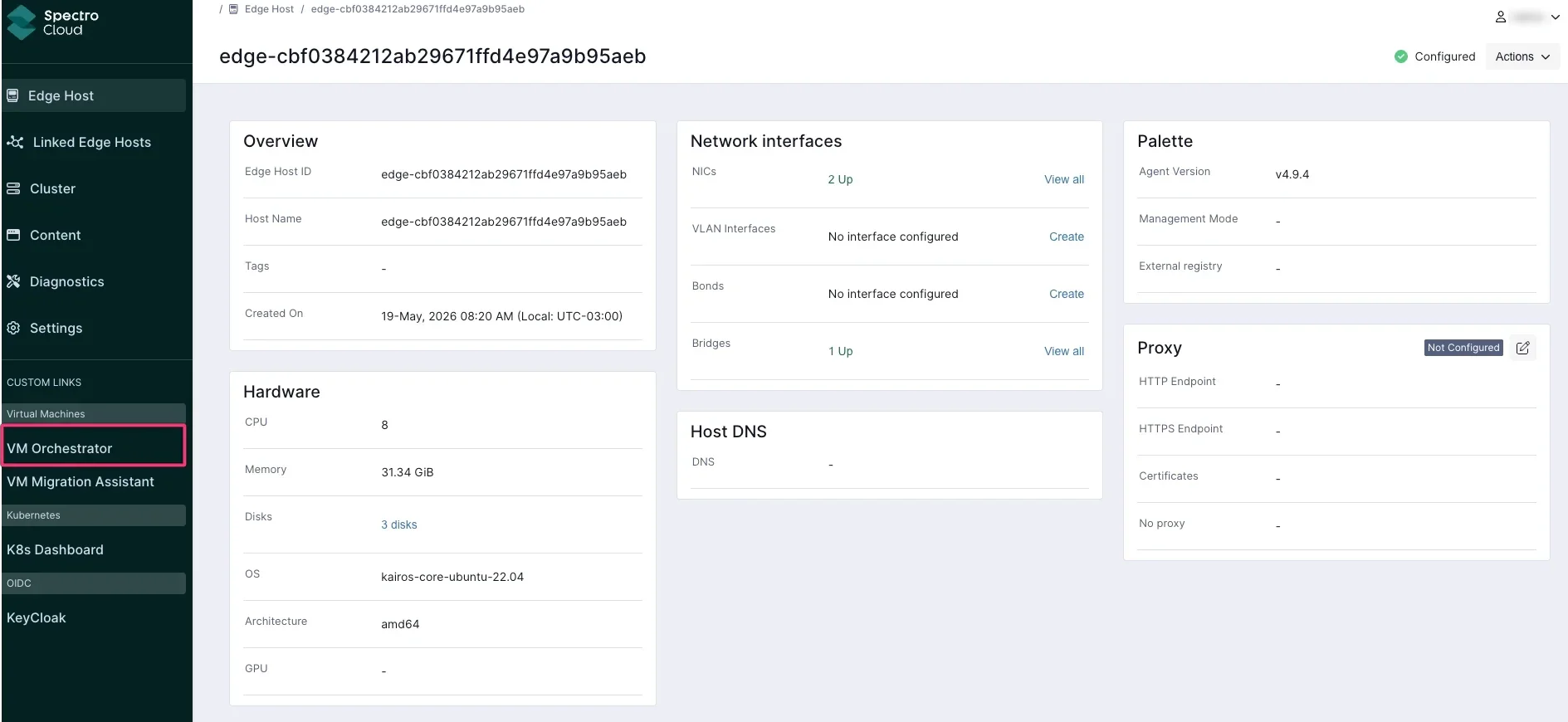
After the cluster deployment is complete, more options appear in the left main menu.
Verify
-
From the left main menu in VM Launchpad, select VM Orchestrator. You can also go to the address you provided for MetalLB in your browser.
-
Log in to VMO Manager.
- Local Auth (Day-0)
- OIDC Using Keycloak
Before you configure Keycloak, use local admin accounts.
- Go to
https://<vmo-address>/local-login. - Enter the local admin username (default:
admin) and the password you configured during cluster creation. - Enter a new password and confirm the new password.
- Select Set New Password.
When Keycloak is configured, VMO Manager uses OIDC for authentication.
- Select Login or go to the platform URL.
- The browser redirects you to the Keycloak login page.
- Enter your username and password.
- After authentication succeeds, the browser redirects you back to VMO Manager.
-
After you log in, the Dashboard is the default landing page.
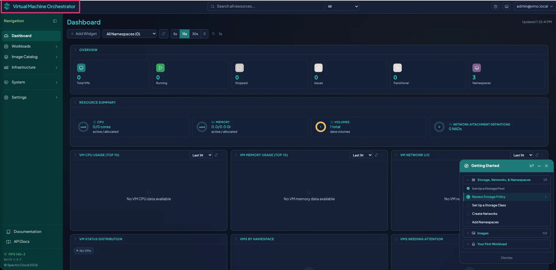
The Dashboard contains a set of adjustable, drag-to-reorder widgets.
Widget Description Overview KPI cards that show Total VMs, Running, Stopped, Issues, Transitional, and Namespace counts. Select a card to filter VMs. Resource Summary CPU and memory cluster usage plus quick links to Data Volumes and Networks. VM CPU Usage (Top 10) Defaults to last 1 hour CPU usage by VMs. VM Memory Usage (Top 10) Defaults to last 1 hour memory usage by VMs. VM Network I/O Defaults to last 1 hour network usage by VMs. VM Status Distribution Breakdown of healthy and unhealthy VMs. VMs by Namespace Breakdown of VMs by running, stopped, and other statuses. VM Needing Attention List of unhealthy VMs.
Auto-Refresh and Pause
The dashboard polls the API and metrics backend on a configurable interval (5 seconds, 15 seconds, or 30 seconds). Use the interval selector in the toolbar to change the cadence. Select Pause to stop all background polling, which is useful when inspecting data or troubleshooting. Select Resume to restart polling.
Customize the Layout
You can customize the interface by dragging widget headers to reorder widgets within the grid, resizing widgets from their bottom-right corner handle, and adding or removing widgets with the + button in the toolbar. Select Reset Layout to return all widgets to the default arrangement. Layout changes save automatically and persist across sessions.
Next Steps
After you deploy your VMO cluster, complete the initial configuration of VM Launchpad, and then create your first VM.