Prepare Network
The information in this guide is provided as general guidance and example configuration only. It may not meet the specific requirements of your environment or cover every possible scenario. Ensure that you tailor these examples and validation steps to the needs of your networking infrastructure.
Preparing your network for Amazon EKS Hybrid Nodes involves configuring both the AWS and remote network environments. You will also need a secure inter-site connection to enable communication between the edge hosts and your Amazon EKS cluster.
The three main areas you need to configure are:
- AWS Network
- Remote Network Environment
- Inter-Site Connectivity
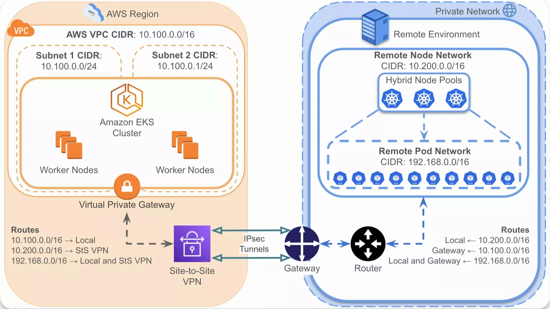
This guide provides common steps and example configurations for each of these areas. The following diagram provides a high-level example of a networking setup for Amazon EKS Hybrid Nodes.
AWS Network
This section provides the steps and example configuration for your AWS network as described in the following AWS documentation:
Prerequisites
-
An AWS account with permissions to view, create, and modify the following resources:
- VPC
- Classless Inter-Domain Routing (CIDR) blocks
- Subnets
- Route tables
- Internet gateways
- Network Address Translation (NAT) gateways
- Elastic IPs
- Security groups
Refer to Amazon VPC policy examples for guidance on Identity and Access Management (IAM) permissions.
Configure AWS Network
-
Create a VPC where the Amazon EKS cluster will be located, for example,
us-east-1. The following table is an example configuration for the VPC.Setting Example Value Name tag eks-hybrid-vpcIPv4 CIDR block IPv4 CIDR manual input IPv4 CIDR 10.100.0.0/16IPv6 CIDR block No IPv6 CIDR block Tenancy Default -
Edit your VPC settings and enable the following options in DNS settings:
- Enable DNS resolution
- Enable DNS hostnames
-
Create two subnets for the VPC that you created. The following table is an example configuration for the subnets.
Setting Example Value for Subnet 1 Example Value for Subnet 2 VPC ID vpc-0518d3603257bf85d (eks-hybrid-vpc)vpc-0518d3603257bf85d (eks-hybrid-vpc)Subnet name eks-hybrid-subnet-1eks-hybrid-subnet-2Availability Zone us-east-1aus-east-1bIPv4 VPC CIDR block 10.100.0.0/1610.100.0.0/16IPv4 subnet CIDR block 10.100.0.0/2410.100.1.0/24 -
If you plan to deploy AWS worker nodes to a public subnet, edit the subnet settings and enable the Enable auto-assign public IPv4 address option.
-
If you want any of your subnets to be public, create and attach an internet gateway to the VPC that you created.
-
For any subnets that you want to keep private, create a NAT gateway for those subnets. The following table is an example configuration for the NAT gateway.
Setting Example Value for Subnet 1 Name eks-hybrid-private-subnet-gatewaySubnet subnet-0cdebdb570d3ca783 (eks-hybrid-subnet-1)Connectivity type Public Elastic IP allocation ID eipalloc-05e4fdafb32b05447The NAT gateway requires an Elastic IP address when setting Connectivity type to Public. Ensure you have already allocated one in the same region as your VPC and subnet. Refer to Allocate an Elastic IP address for guidance.
-
Edit the main route table depending on whether your subnets will be private or public. The main route table is created automatically for the subnets within the VPC.
If you want one private subnet and one public subnet, follow the steps to edit the main route table for your private subnet first. Then, create a custom route table for your VPC and configure it for your public subnet.
- Private
- Public
- Associate the subnet or subnets with your route table explicitly.
- Add a route to your NAT gateway.
- Ensure that a
localroute exists for your VPC CIDR. - (Optional) Provide a Name tag for your route table, for example,
eks-hybrid-private-subnet-rt.
Example route table
Destination Target Status Propagated 0.0.0.0/0nat-0327bf58440ab78b9Active No 10.100.0.0/16localActive No - Associate the subnet or subnets with your route table explicitly.
- Add a route to your internet gateway.
- Ensure that a
localroute exists for your VPC CIDR. - (Optional) Provide a Name tag for your route table, for example,
eks-hybrid-public-subnet-rt.
Example route table
Destination Target Status Propagated 0.0.0.0/0igw-0ddc77da7524bf133Active No 10.100.0.0/16localActive No -
Create a security group for your VPC that contains the necessary rules to allow communication with your remote environment. This security group is added as an additional security group when creating your EKS cluster as described in the Prepare EKS Cluster steps.
The following tables are an example configuration for the security group.
- Basic Details
- Inbound Rules
- Outbound Rules
Setting Example Value Security group name eks-hybrid-remote-rules-sgDescription (optional) "EKS Hybrid remote environment communication" VPC vpc-0518d3603257bf85d (eks-hybrid-vpc)Tags (optional) Name=eks-hybrid-remote-rules-sgType Protocol Port Range Source Description (optional) HTTPS TCP 443 10.200.0.0/16"Remote Node CIDR Inbound" HTTPS TCP 443 192.168.0.0/16"Remote Pod CIDR Inbound" Optionally, you can enable SSH and ICMP access from your on-prem/remote network as described in the AWS Site-to-Site VPN - Update your security group step.
Type Protocol Port Range Source Description (optional) SSH TCP 22 10.200.0.0/16"Remote Node CIDR SSH Inbound" All ICMP - IPv4 ICMP All 10.200.0.0/16"Remote Node CIDR ICMP Inbound" Type Protocol Port Range Destination Description (optional) Custom TCP TCP 10250 10.200.0.0/16"Remote Node CIDR Outbound" HTTPS TCP 443 192.168.0.0/16"Remote Pod CIDR Webhook Outbound"
Validate
-
Log in to AWS.
-
Check that your created network resources have a State of Available or Attached in the chosen region. A list of the expected resources is as follows:
- AWS VPC for your Amazon EKS cluster.
- Two subnets within the AWS VPC.
- Internet gateways for your public subnets.
- NAT gateways for your private subnets.
-
Check that you have created the following additional resources:
- Route tables for your subnets.
- Default security group for your VPC and custom security group for your remote environment.
- Elastic IPs for your NAT gateways, if any.
Remote Network Environment
This section provides high-level steps and example configuration for your remote network environment as described in the AWS documentation under On-premises networking configuration.
Prerequisites
-
Access to your on-prem/remote core network devices with sufficient privileges to create and modify network configurations. This includes the following:
-
Permissions to define or adjust IP address allocations in the on-prem/remote environment to avoid CIDR overlap with AWS VPCs.
-
Permissions to configure or update firewall rules and NAT settings.
-
Configure Remote Network
-
Configure your Virtual Local Area Network (VLAN) or subnet definitions to a suitable IP range for your hybrid nodes. Refer to On-premises node and pod CIDRs for AWS requirements on CIDR blocks in remote networks.
- Example hybrid node CIDR block =
10.200.0.0/16- Example hybrid node subnets =
10.200.0.0/24,10.200.1.0/24
- Example hybrid node subnets =
- Example pod CIDR block =
192.168.0.0/16
- Example hybrid node CIDR block =
-
Configure your NAT settings to allow outbound internet access from your hybrid nodes or, at a minimum, access to the necessary AWS services for hybrid node installation and upgrade.
The following tables are an example list of enabled service URLs in the
us-east-1region. All endpoints are accessed with theHTTPSprotocol on port443. The services vary depending on the credential model used for the hybrid nodes.- AWS Service Manager (SSM)
- AWS IAM Roles Anywhere
Service Endpoint URL Amazon EKS https://hybrid-assets.eks.amazonaws.comAmazon EKS https://eks.us-east-1.amazonaws.comAmazon ECR https://api.ecr.us-east-1.amazonaws.comAmazon EKS ECR https://602401143452.dkr.ecr.us-east-1.amazonaws.comAWS Systems Manager (SSM) https://amazon-ssm-us-east-1.s3.us-east-1.amazonaws.comAWS Systems Manager (SSM) https://ssm.us-east-1.amazonaws.com(Optional) AWS Systems Manager (SSM) https://ec2messages.us-east-1.amazonaws.com(Optional) Amazon CloudWatch Logs https://logs.us-east-1.amazonaws.com(Optional) Amazon S3 https://s3.us-east-1.amazonaws.comService Endpoint URL Amazon EKS https://hybrid-assets.eks.amazonaws.comAmazon EKS https://eks.us-east-1.amazonaws.comAmazon ECR https://api.ecr.us-east-1.amazonaws.comAmazon EKS ECR https://602401143452.dkr.ecr.us-east-1.amazonaws.comAWS IAM Roles Anywhere https://rolesanywhere.amazonaws.comAWS IAM Roles Anywhere https://rolesanywhere.us-east-1.amazonaws.com(Optional) AWS IAM https://iam.amazonaws.com(Optional) AWS Security Token Service (STS) https://sts.us-east-1.amazonaws.com(Optional) Amazon CloudWatch Logs https://logs.us-east-1.amazonaws.com(Optional) Amazon S3 https://s3.us-east-1.amazonaws.com -
Configure your firewall rules to allow node and pod communication with necessary AWS services as described in Access required for ongoing cluster operations.
The following tables are example on-prem/remote firewall rules for AWS services.
- Inbound Rules
- Outbound Rules
Protocols Port Range Source Destination Description TCP 10250 10.100.0.0/1610.200.0.0/16Amazon EKS cluster to hybrid nodes. TCP 443 10.100.0.0/16192.168.0.0/16Amazon EKS cluster to hybrid pods. TCP, UDP 53 192.168.0.0/16192.168.0.0/16Hybrid pods to CoreDNS. TCP, UDP 443 192.168.0.0/16192.168.0.0/16Hybrid pod to hybrid pod application port. SSH 22 10.100.0.0/1610.200.0.0/16(Optional) Amazon EKS VPC CIDR to hybrid nodes for SSH access. ICMP - IPv4 All 10.100.0.0/1610.200.0.0/16(Optional) Amazon EKS VPC CIDR to hybrid nodes for ICMP access. The outbound rules vary depending on the credential model used for the hybrid nodes.
- AWS Service Manager (SSM)
- AWS IAM Roles Anywhere
Protocols Port Range Source Destination Description TCP 443 10.200.0.0/1610.100.0.0/16Hybrid nodes to Amazon EKS cluster. TCP 443 192.168.0.0/1610.100.0.0/16Hybrid pods to Amazon EKS cluster. TCP 443 10.200.0.0/16https://ssm.us-east-1.amazonaws.comHybrid nodes to AWS SSM. TCP 443 10.200.0.0/16https://eks.us-east-1.amazonaws.comHybrid nodes to Amazon EKS Pod Identity. TCP, UDP 53 192.168.0.0/16192.168.0.0/16CoreDNS to hybrid pods. TCP, UDP 443 192.168.0.0/16192.168.0.0/16Hybrid pod to hybrid pod application port. Protocols Port Range Source Destination Description TCP 443 10.200.0.0/1610.100.0.0/16Hybrid nodes to Amazon EKS cluster. TCP 443 192.168.0.0/1610.100.0.0/16Hybrid pods to Amazon EKS cluster. TCP 443 10.200.0.0/16https://rolesanywhere.us-east-1.amazonaws.comHybrid nodes to AWS IAM Roles Anywhere. TCP 443 192.168.0.0/16https://sts.us-east-1.amazonaws.comHybrid pods to AWS STS. TCP 443 10.200.0.0/16https://eks.us-east-1.amazonaws.comHybrid nodes to Amazon EKS Pod Identity. TCP, UDP 53 192.168.0.0/16192.168.0.0/16CoreDNS to hybrid pods. TCP, UDP 443 192.168.0.0/16192.168.0.0/16Hybrid pod to hybrid pod application port. -
Configure firewall rules for Cilium operation. Cilium is used as the Container Network Interface (CNI) for hybrid nodes and requires firewall rules to allow health checks, Virtual Extensible Local Area Network (VXLAN) overlay, and etcd access.
The following tables are example on-prem/remote firewall rules for Cilium and assumes that hybrid nodes will act as worker nodes without VXLAN overlay networking.
- Ingress Rules
- Egress Rules
Protocol Port Range Source Destination Description TCP 4240 10.100.0.0/1610.200.0.0/16AWS to hybrid node for cilium-healthmonitoring.TCP 4240 10.200.0.0/1610.200.0.0/16Hybrid node to hybrid node for cilium-healthmonitoring.ICMP Type 0/8, Code 0 10.100.0.0/1610.200.0.0/16AWS to hybrid node pings for cilium-health.ICMP Type 0/8, Code 0 10.200.0.0/1610.200.0.0/16Hybrid node to hybrid node pings for cilium-health.Protocol Port Range Source Destination Description TCP 4240 10.200.0.0/1610.100.0.0/16Hybrid node to AWS for cilium-healthmonitoring.TCP 4240 10.200.0.0/1610.200.0.0/16Hybrid node to hybrid node for cilium-healthmonitoring.ICMP Type 0/8, Code 0 10.200.0.0/1610.100.0.0/16Hybrid node to AWS pings for cilium-health.ICMP Type 0/8, Code 0 10.200.0.0/1610.200.0.0/16Hybrid node to hybrid node pings for cilium-health.TCP 2379-2380 10.200.0.0/1610.100.0.0/16Hybrid node to Amazon EKS for etcd access. -
Configure firewall rules for Palette SaaS operation, which requires inbound and outbound connectivity to Palette SaaS services and ports.
Validate
-
Log in to your on-prem/remote network device or network management tool.
-
Check that the following network resources have been configured for hybrid nodes.
- VLAN or subnets defined for appropriate IP ranges for hybrid nodes.
- NAT settings for outbound access to AWS services.
- Firewall rules for AWS services and Cilium operations.
-
(Optional) If you have an available host deployed within the VLAN or subnet, SSH into the host, and verify the host can connect to the required AWS and Spectro Cloud services.
For example, if you have netcat installed, issue the following command on the Edge host to check whether the
eks.us-east-1.amazonaws.comdomain is accessible on port443.nc -z -v eks.us-east-1.amazonaws.com 443Example output, if successful.
Connection to eks.us-east-1.amazonaws.com port 443 [tcp/https] succeeded!
Inter-Site Connectivity
This section outlines high-level steps and example configurations for establishing inter-site connectivity between AWS and your on-prem/remote environment.
Inter-site connectivity can be configured using a variety of methods, such as:
Refer to Network-to-Amazon VPC connectivity options for guidance on all available options.
This section's primary focus is AWS Site-to-Site VPN, although some steps can be adapted for AWS Direct Connect.
Prerequisites
-
An AWS account with permissions to view, create, and modify the following resources:
- Route tables
- Transit gateways or Virtual private gateways, or both
- Security groups
- Customer gateway
- Site-to-Site VPN or Direct Connect
Refer to Amazon VPC policy examples for guidance on Identity and Access Management (IAM) permissions.
-
Access to your on-prem/remote core network devices with sufficient privileges to create and modify network configurations. This includes the following:
-
If using a VPN, permissions to configure or update IPsec tunnels/security policies.
-
If using an IPsec VPN or similar encrypted connection, permissions to generate, install, and rotate certificates or keys on the local network equipment.
-
If using a VPN, permissions to update firewall rules for VPN ports.
-
Permissions to adjust or introduce Border Gateway Protocol (BGP) or manage static routes that control traffic to and from AWS.
-
-
The network connectivity between AWS and on-prem/remote environment meets the recommended minimum network requirements.
Configure Inter-Site Connectivity
-
In AWS, create a customer gateway.
The following table is an example configuration for the customer gateway. Refer to Customer gateway options for your AWS Site-to-Site VPN connection for further guidance on all available options.
Setting Example Value Description Name tag (optional) eks-hybrid-remote-gateway-1The optional AWS Name tag value for the customer gateway. BGP ASN 65000The BGP Autonomous System Number (ASN) used to identify your on-prem/remote gateway in BGP route exchanges. It must be distinct from the ASN configured on the AWS target gateway. IP address 3.232.157.211The public IP address of the on-prem/remote gateway used to establish the VPN connection. Device (optional) eks-hybrid-remote-gateway-1An optional identifier for the device, used for reference within the AWS console. -
In AWS, create a target gateway and attach it to your VPC. Virtual private gateways are attached to a single VPC, whereas transit gateways can facilitate multiple VPCs.
importantIf you are planning to use AWS Direct Connect, ensure that you create the gateway in the AWS Direct Connect console. If using AWS Site-to-Site VPN, create the gateway in the AWS VPC console.
The following tables are example configurations for the target gateway.
- Virtual Private Gateway
- Transit Gateway & Attachment
Setting Example Value Description Name tag (optional) eks-hybrid-vgwThe optional AWS Name tag value for the virtual private gateway. Autonomous System Number (ASN) Amazon default ASN A unique numeric identifier that the AWS gateway uses in BGP route exchanges. This ASN must be distinct from the customer gateway ASN. Attach to VPC vpc-0518d3603257bf85d (eks-hybrid-vpc)The AWS VPC that the virtual private gateway is attached to. In the AWS Console, this step is performed after creating the virtual private gateway. If using this type of target gateway, you must create a transit gateway and a transit gateway attachment. Create the transit gateway first as you must specify it when creating the transit gateway attachment.
- Transit Gateway
- Transit Gateway Attachment
Setting Example Value Description Name tag (optional) eks-hybrid-tgwThe optional AWS Name tag value for the transit gateway. Description "Transit Gateway for EKS Hybrid" User-defined description for the transit gateway. Amazon side Autonomous System Number (ASN) 64513A unique numeric identifier that the AWS gateway uses in BGP route exchanges. This ASN must be distinct from the customer gateway ASN. DNS support ✅ Enables DNS resolution for attached VPCs through the transit gateway. VPN ECMP support ✅ Allows Equal-Cost Multi-Path (ECMP) routing for VPN connections, which improves load-balancing traffic across multiple paths. Default route table association ✅ Specifies that new attachments are automatically associated with the default transit gateway route table. Default route table propagation ✅ Specifies that routes from attachments are automatically propagated to the default transit gateway route table. Setting Example Value Description Name tag (optional) eks-hybrid-tgw-vpc-attachmentThe optional AWS Name tag value for the transit gateway. Transit gateway ID tgw-06e39deb85a158d2e (eks-hybrid-tgw)The identifier for the transit gateway. Attachment type VPC The attachment type for the transit gateway attachment. DNS support ✅ Enables DNS resolution through the transit gateway for this attachment. Security Group Referencing support ✅ Allows referencing of security groups across the VPC attachment, supporting cross-VPC security group rules. VPC ID vpc-0518d3603257bf85d (eks-hybrid-vpc)Specifies that new attachments are automatically associated with the default transit gateway route table. Subnet IDs ✅ us-east-1a - subnet-0cdebdb570d3ca783 (eks-hybrid-subnet-1)
✅ us-east-1b -subnet-01fb42f5764dcf18e (eks-hybrid-subnet-2)The specific subnets in the VPC used by the attachment. -
Configure routing in AWS to enable traffic from your on-prem/remote network.
infoIf using AWS Direct Connect, you would need to map traffic from your on-prem/remote network to your AWS VPC private subnet CIDRs.
For example, both remote node and pod CIDRs10.200.0.0/16and192.168.0.0/16→ Private subnet CIDRs10.100.0.0/24and10.100.1.0/24.-
If using a virtual private gateway, enable route propagation on your subnet route tables.
-
If using static routing, once your IPsec tunnels have been established later on in step 7, the remote node and remote pod CIDR routes should automatically propagate to your subnet route tables.
Example
Destination Target Status Propagated 10.200.0.0/16vgw-08b7d849217105d6fActive Yes 192.168.0.0/16vgw-08b7d849217105d6fActive Yes If they are not automatically propagated, you will need to define them manually.
-
-
If using a transit gateway, add two routes to your subnet route tables and your transit gateway route table.
-
For the subnet route tables, add routes that target the transit gateway for traffic destined for the remote node CIDRs and remote pod CIDRs.
Example
Destination Target Status Propagated 10.200.0.0/16tgw-06e39deb85a158d2eActive No 192.168.0.0/16tgw-06e39deb85a158d2eActive No -
For the transit gateway route table, create active static routes for the remote node CIDRs and remote pod CIDRs. These should be attached to the VPN.
Example
CIDR Attachment ID Resource ID Resource type Route type Route state 10.200.0.0/16tgw-attach-0b80c5b8aff518eadvpn-0c3568c2303ac18df(3.232.157.211)VPN Static Active 192.168.0.0/16tgw-attach-0b80c5b8aff518eadvpn-0c3568c2303ac18df(3.232.157.211)VPN Static Active
-
-
-
Create a VPN connection in AWS.
The following tables are example configurations for an AWS Site-to-Site VPN depending on the target gateway type.
- Virtual Private Gateway
- Transit Gateway
Setting Example Value Description Name tag (optional) eks-hybrid-sts-vpnThe optional AWS Name tag value for the Site-to-Site VPN. Target gateway type Virtual private gateway The target gateway type. This should match what you created in step 2. Virtual private gateway vgw-08b7d849217105d6f (eks-hybrid-vgw)The virtual private gateway for the Amazon EKS VPC. Customer gateway Existing Choose Existing to be able to select the customer gateway created in step 1. Customer gateway ID cgw-0b4ec7c65c5189d1e (eks-hybrid-remote-gateway-1)The customer gateway for your on-prem/remote gateway connection. Routing options Static Whether to use dynamic or static routing. Static IP prefixes 10.200.0.0/16,192.168.0.0/16If using static routing, the remote node CIDR and remote pod CIDR must be added here. Setting Example Value Description Name tag (optional) eks-hybrid-sts-vpnThe optional AWS Name tag value for the Site-to-Site VPN. Target gateway type Transit gateway The target gateway type. This should match what you created in step 2. Transit gateway tgw-06e39deb85a158d2e (eks-hybrid-tgw)The transit gateway for the Site-to-Site VPN connection. Customer gateway Existing Choose Existing to be able to select the customer gateway created in step 1. Customer gateway ID cgw-0b4ec7c65c5189d1e (eks-hybrid-remote-gateway-1)The customer gateway for your on-prem/remote gateway connection. Routing options Dynamic (requires BGP) Whether to use dynamic or static routing. Tunnel inside IP version IPv4 The type of traffic that the VPN tunnels will support. Outside IP address type PublicIpv4 The type of IP address used for the VPN tunnel's outside interface. This should be set to PublicIpv4 unless you are creating a VPN connection over AWS Direct Connect. -
Download the configuration file to help you configure your on-prem/remote gateway device.
Example download configuration
Setting Example Value Vendor pfSense Platform pfSense Software pfsense 2.2.5+(GUI) IKE version ikev1 -
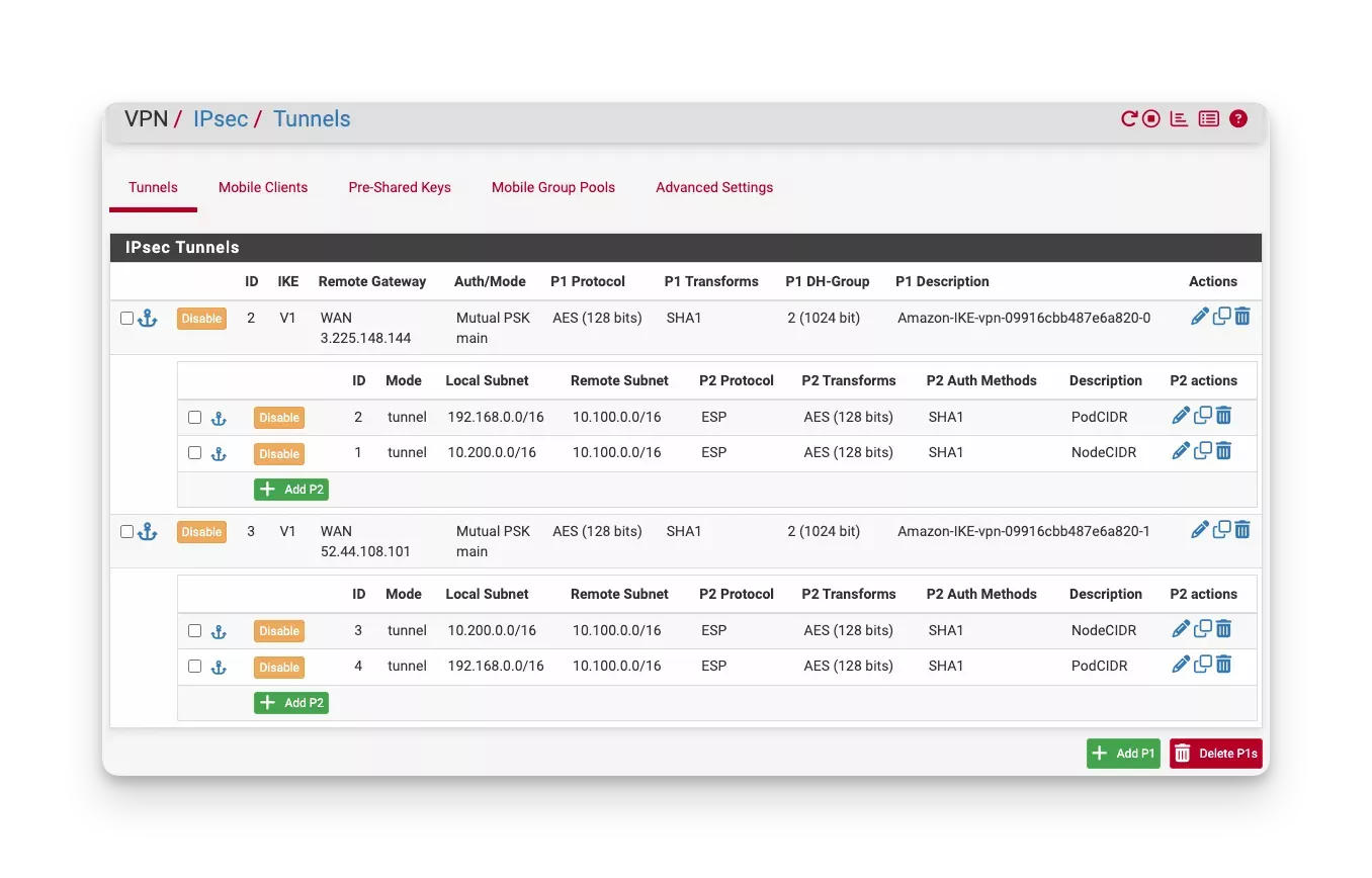
On your on-prem/remote VPN gateway, configure IPsec Phase 1 tunnels with Phase 2 security associations to establish a connection to your AWS VPN. The Phase 2 security associations need to include the following routes:
-
Hybrid node network CIDR to AWS VPC CIDR.
- This can be split into multiple routes for each hybrid node subnet. If doing so, ensure that the AWS VPN has paired traffic selectors configured. If using an AWS Site-to-Site VPN, this would be configured through the Local IPv4 Network CIDR and Remote IPv4 Network CIDR settings.
-
Hybrid pod network CIDR to AWS VPC CIDR.
The following screenshot shows an example IPsec tunnel configuration on a pfSense device.
-
-
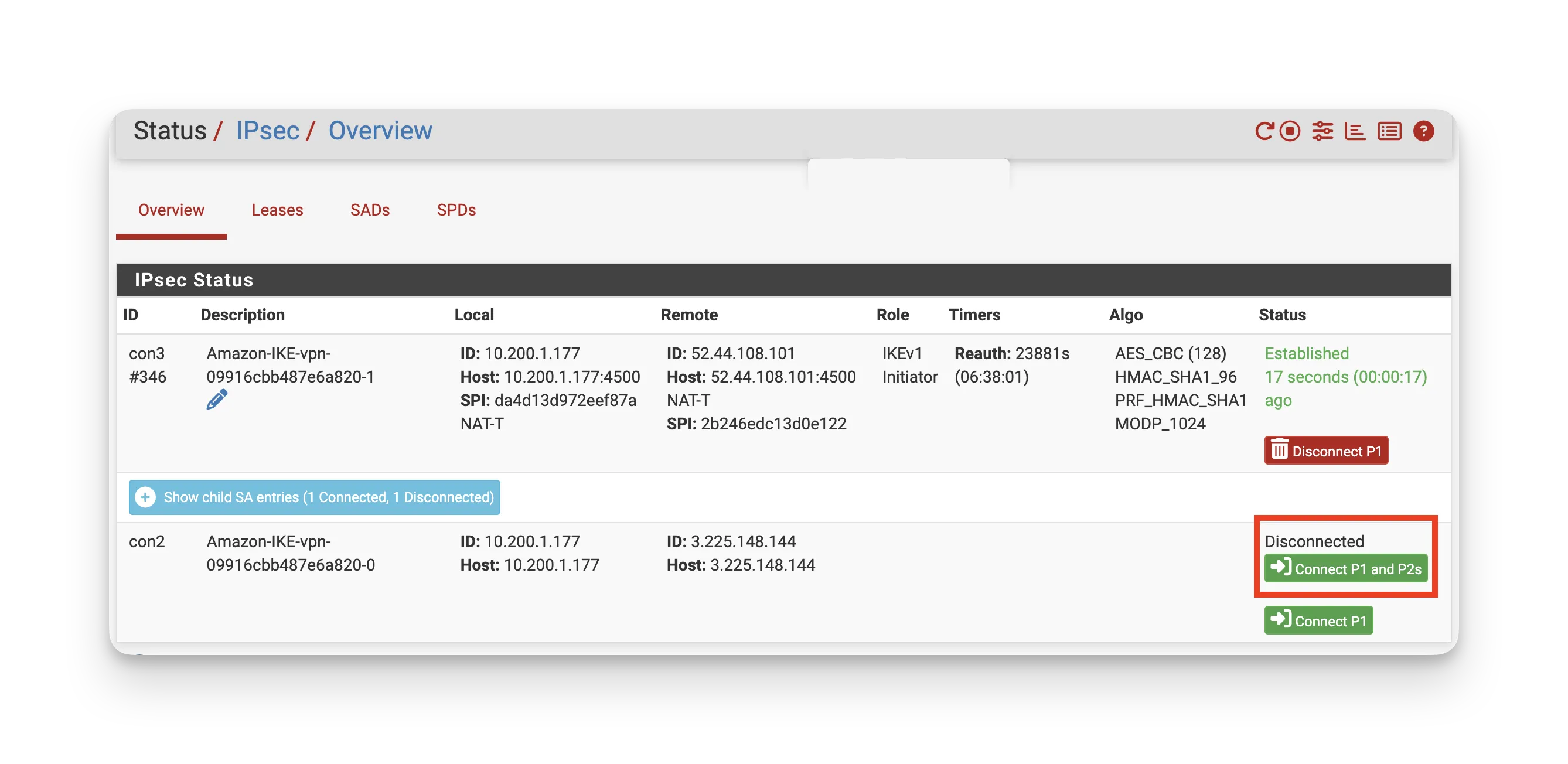
Ensure that your IPsec tunnels have a connection established on your on-prem/remote VPN gateway for both phase 1 and phase 2 connections. The following screenshot shows an example of a connected and disconnected tunnel on a pfSense device.
-
Configure your on-prem/remote firewall rules to allow VPN traffic. You will need to configure rules for each IPsec tunnel.
The following tables describe example firewall rules where
52.44.108.101and3.225.148.144are example Outside IP Address entries for AWS Site-to-Site VPN Tunnels.- Inbound Rules
- Outbound Rules
Protocol Port Source Description UDP 1194 52.44.108.101,3.225.148.144OpenVPN traffic. UDP 500 52.44.108.101,3.225.148.144IKE Phase 1 for IPsec VPN. UDP 4500 52.44.108.101,3.225.148.144NAT-Traversal (NAT-T) for IPsec VPN. ESP (IP 50) N/A 52.44.108.101,3.225.148.144Encapsulating Security Payload (ESP) for IPsec data encryption. Protocol Port Destination Description UDP 1194 52.44.108.101,3.225.148.144OpenVPN traffic. UDP 500 52.44.108.101,3.225.148.144IKE Phase 1 for IPsec VPN. UDP 4500 52.44.108.101,3.225.148.144NAT-Traversal (NAT-T) for IPsec VPN. ESP (IP 50) N/A 52.44.108.101,3.225.148.144Encapsulating Security Payload (ESP) for IPsec data encryption. -
Ensure that the appropriate NAT exemptions or policies, such as IPsec passthrough, are configured so that IPsec traffic is not inadvertently translated.
-
Configure your on-prem/remote router to ensure network traffic to and from AWS reaches the correct hybrid nodes.
In both BGP and static routing scenarios, a route must exist to send all Amazon EKS VPC-bound traffic through a centralized VPN gateway.
- Border Gateway Protocol (BGP)
- Static Routing
-
Use BGP to share your remote node and pod CIDRs with AWS.
- If using AWS Direct Connect, this may be all that is required as AWS can route directly to individual on-prem/remote nodes.
-
Automate local route advertisement so your on-prem/remote routers dynamically learn each node’s CIDR, removing the need for manual route management.
- Refer to the Cilium BGP documentation for comprehensive setup details and best practices.
-
In VPN setups where AWS routes all traffic to a single on-prem VPN server, rely on BGP to direct traffic to the correct on-prem/remote nodes or set up static routes as needed.
- Static routes are configured during the Configure Hybrid Node Networking for VPN Solutions steps.
-
Optionally, you can define a unique VPN server IP for each hybrid node as a fallback during the Create Hybrid Node Pool steps.
- If your on-prem/remote gateway or default gateway does not automatically route traffic bound for the AWS VPC CIDR to the VPN server, even when BGP is used, this feature ensures each node can still reach out to AWS. This is not necessary if the network already has the proper route to the AWS VPC CIDR.
-
Static routes are configured during the Configure Hybrid Node Networking for VPN Solutions steps.
-
Optionally, you can define a unique VPN server IP for each hybrid node during the Create Hybrid Node Pool steps to maintain granular routing control.
- If your on-prem/remote gateway or default gateway does not automatically route traffic bound for the AWS VPC CIDR to the VPN server, this feature ensures each node can reach out to AWS.
Validate
- AWS Site-to-Site VPN
- AWS Direct Connect
-
Log in to the Amazon VPC console.
-
Check that your AWS Site-to-Site VPN connection has two tunnels with a Status of Up.
-
If you have an available host deployed within the on-prem/remote VLAN or subnet, SSH into the host, and attempt to reach your AWS VPC gateway.
Replace
<awsVpcGateway>with the IP address of your AWS VPC gateway, for example,10.100.0.1.ping <awsVpcGateway>Check that the ping statistics from the output show a healthy connection.
Example healthy output.
PING 10.100.0.1 (10.100.0.1) 56(84) bytes of data.
64 bytes from 10.100.0.1: icmp_seq=1 ttl=64 time=27.5 ms
64 bytes from 10.100.0.1: icmp_seq=2 ttl=64 time=28.2 ms
64 bytes from 10.100.0.1: icmp_seq=3 ttl=64 time=29.1 ms
64 bytes from 10.100.0.1: icmp_seq=4 ttl=64 time=27.9 ms
--- 10.100.0.1 ping statistics ---
4 packets transmitted, 4 received, 0% packet loss, time 3999ms
rtt min/avg/max/mdev = 27.5/28.2/29.1/0.6 ms -
If you have an EC2 instance available that has been deployed in your AWS VPC, SSH into the instance, and attempt to reach an available host deployed within the on-prem/remote VLAN or subnet.
Replace
<hostIpAddress>with the IP address of your on-prem/remote host, for example,10.200.1.23.ping <hostIpAddress>Check that the ping statistics from the output show a healthy connection.
Example healthy output.
PING 10.200.1.23 (10.200.1.23) 56(84) bytes of data.
64 bytes from 10.200.1.23: icmp_seq=1 ttl=64 time=27.5 ms
64 bytes from 10.200.1.23: icmp_seq=2 ttl=64 time=28.2 ms
64 bytes from 10.200.1.23: icmp_seq=3 ttl=64 time=29.1 ms
64 bytes from 10.200.1.23: icmp_seq=4 ttl=64 time=27.9 ms
--- 10.200.1.23 ping statistics ---
4 packets transmitted, 4 received, 0% packet loss, time 3999ms
rtt min/avg/max/mdev = 27.5/28.2/29.1/0.6 ms
-
Log in to the AWS Direct Connect console.
-
Check that the AWS Direct Connect connection and its associated Virtual Interface (Private VIF) are in an Available state. Check that the BGP session is established and the BGP status is Up.
-
If you have an available host deployed within the on-prem/remote VLAN or subnet, SSH into the host, and attempt to reach your AWS VPC gateway.
Replace
<awsVpcGateway>with the IP address of your AWS VPC gateway, for example,10.100.0.1.ping <awsVpcGateway>Check that the ping statistics from the output show a healthy connection.
Example healthy output.
PING 10.100.0.1 (10.100.0.1) 56(84) bytes of data.
64 bytes from 10.100.0.1: icmp_seq=1 ttl=64 time=27.5 ms
64 bytes from 10.100.0.1: icmp_seq=2 ttl=64 time=28.2 ms
64 bytes from 10.100.0.1: icmp_seq=3 ttl=64 time=29.1 ms
64 bytes from 10.100.0.1: icmp_seq=4 ttl=64 time=27.9 ms
--- 10.100.0.1 ping statistics ---
4 packets transmitted, 4 received, 0% packet loss, time 3999ms
rtt min/avg/max/mdev = 27.5/28.2/29.1/0.6 ms -
If you have an EC2 instance available that has been deployed in your AWS VPC, attempt to reach an available host deployed within the on-prem/remote VLAN or subnet.
Replace
<hostIpAddress>with the IP address of your on-prem/remote host, for example,10.200.1.23.ping <hostIpAddress>Check that the ping statistics from the output show a healthy connection.
Example healthy output.
PING 10.200.1.23 (10.200.1.23) 56(84) bytes of data.
64 bytes from 10.200.1.23: icmp_seq=1 ttl=64 time=27.5 ms
64 bytes from 10.200.1.23: icmp_seq=2 ttl=64 time=28.2 ms
64 bytes from 10.200.1.23: icmp_seq=3 ttl=64 time=29.1 ms
64 bytes from 10.200.1.23: icmp_seq=4 ttl=64 time=27.9 ms
--- 10.200.1.23 ping statistics ---
4 packets transmitted, 4 received, 0% packet loss, time 3999ms
rtt min/avg/max/mdev = 27.5/28.2/29.1/0.6 ms
Next Steps
Complete the remaining sections as highlighted in Prepare Environment.